The blood is pumped by Heart
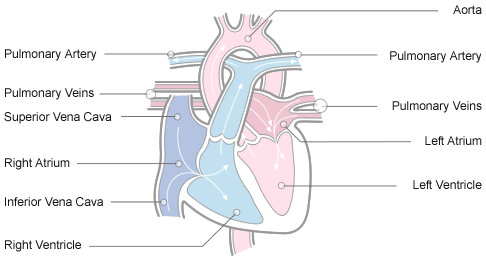
The heart itself is made up of 4 chambers, 2 atria and 2 ventricles. heart studies have shown that De-oxygenated blood returns to the right side of the heart via venous circulation. the heart pumps blood into the right ventricle and then to the lungs where carbon dioxide is released and oxygen is absorbed. The oxygenated blood then travels back to the left side of the heart into the left atria, then into the left ventricle from where blood is pumped into the aorta and arterial circulation.
Image: The passage of blood through the heart
The pressure created in the arteries by the contraction of the left ventricle is the systolic blood pressure. Once the left ventricle has fully contracted it begins to relax and refill with blood from the left atria. The pressure in the arteries falls whilst the ventricle refills. This is the diastolic blood pressure.
The atrio-ventricular septum completely separates the 2 sides of the heart. Unless there is a septal defect, the 2 sides of the heart never directly communicate. Blood travels from right side to left side via the lungs only. However the chambers themselves work together . The 2 atria contract simultaneously, and the 2 ventricles contract simultaneously.
Cardiac Conduction System
Continuing with the analogy of a central heating system, the pump, pipes, and radiators are useless without a power source. Similarly, the heart requires electrical energy to function. Just as the heating system needs power, the heart relies on electrical impulses to pump blood. Fortunately, unlike machines, we don’t need to plug into an external power supply—our heart generates its own electrical signals and directs them through a specialized conduction pathway.
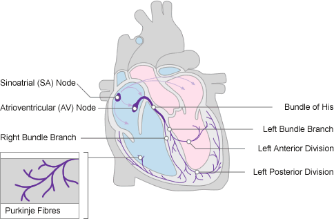
This conduction system consists of five key components:
- Sinoatrial (SA) node
- Atrioventricular (AV) node
- Bundle of His
- Left and right bundle branches
- Purkinje fibers
Illustration: The cardiac conduction system.
The sinoatrial (SA) node functions as the heart’s intrinsic pacemaker. In cases where the SA node becomes dysfunctional, medical interventions such as permanent pacemakers (PPMs) or temporary pacing wires (TPWs) are employed to regulate heart rhythm.
The SA node generates electrical impulses at a frequency that aligns with the body’s metabolic demands. These impulses propagate through the myocardial cells of the atria, resulting in a coordinated contraction wave that rapidly travels across both atria.
To illustrate, envision a sequence of falling dominoes: once one domino is tipped, it triggers a cascading effect that continues until the entire pattern has collapsed. In the heart, approximately half a billion cells participate in this process. Most of the myocardial cells are located within the ventricular walls. When the heart contracts, nearly 100 million atrial cells are activated in less than one-third of a second, producing a contraction that appears instantaneous.
The electrical signal from the SA node eventually reaches the atrioventricular (AV) node, where it is momentarily delayed. This delay ensures the atria have sufficient time to empty their blood into the ventricles. Following atrial contraction and valve closure between the atria and ventricles, the atria begin to refill, while the electrical impulse progresses through the AV node and into the Bundle of His, bundle branches, and Purkinje fibers.
Using another analogy, the bundle branches act as highways, and the Purkinje fibers function as smaller roads, distributing the electrical impulse across the ventricles. This ensures the simultaneous contraction of the roughly 400 million myocardial cells that form the ventricular walls. As the ventricles contract, blood is pumped to the lungs via the right ventricle for gas exchange, and the left ventricle pumps oxygenated blood into the aorta, supplying the systemic and coronary circulation.
At this point, the ventricles are emptied of blood, the atria are full, and the valves between them are closed. The SA node is primed to release another impulse, initiating a new cardiac cycle. However, the SA and AV nodes must undergo a recovery phase after each discharge. Similar to refilling a bucket of water after it’s emptied, both nodes must “recharge” before they can release another electrical signal.
In the heart, the SA node recharges while the atria refill, and the AV node recharges as the ventricles refill. This continuous cycle allows the heart to function without interruption, with each beat completing in less than a third of a second.
At a resting heart rate of 60 beats per minute, or one beat per second, the three distinct phases of the cardiac cycle can be described as:
- Depolarization – The discharge of an electrical impulse.
- Contraction – The mechanical response of myocardial cells.
- Repolarization – The recharge phase, preparing the nodes for the next impulse.
These phases constitute the full cardiac cycle, maintaining efficient blood circulation throughout the body.
- Atrial depolarisation
- Ventricular depolarisation
- Atrial and ventricular repolarisation
Role of the ECG Machine
The ECG machine is designed to recognise and record any electrical activity within the heart. It prints out this information on ECG paper made up of small squares 1mm squared.
Image: ECG paper
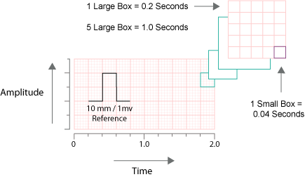
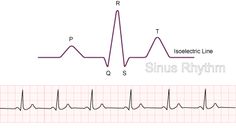
Each electrical stimulus takes the form of a wave and so patterns emerge made up of a number of connected waves. A standard ECG is printed at 25mm per second or 25 small squares per second (see above). In this way it is possible to calculate the duration of individual waves.
10 small squares vertically is equal to 1 millivolt. So it is possible to calculate the amount of voltage being released within the heart. If the line is flat at any time in the duration of a series of waves, it indicates no electrical activity at that particular moment.
The direction in which the waves point indicates whether electricity is moving towards or away from a particular lead.
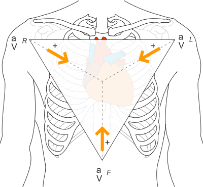
The general direction in which electricity normally travels through the heart is a downward diagonal line from the right shoulder to the left lower abdomen. This is because the electrical stimulus originates in the SA node (upper right side of the heart), travels through the AV node and bundle of His, and finishes mainly in the left ventricle. (remember that there is more conduction in the left ventricle).
So different leads may have waves pointing in different directions. Eg. Lead AVR (right shoulder/right arm/wrist) will always see the electrical stimulus travelling away from it, therefore the waves expressed in AVR for sinus rhythm, pqrst, will all point downwards.
Image: Rhythm strip of sinus rhythm recorded from ECG lead AVR

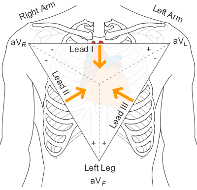
ECG Lead Placement
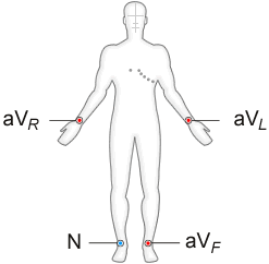
The system of positioning of leads for performing a 12-lead ECG is universal. This helps to ensure that, when a person’s ECGs are compared, any changes on the ECG are due to cardiac injury, not a difference in placement of leads, this is extremely important with the increasing use of foreign travel. There are universal standards in place throughout the world.
Interpretation of the findings can vary from doctor to doctor but methods for obtaining the information are the same the world over.
These positions may differ slightly when a patient is on continuous cardiac monitoring. The leads routinely attached to wrists and ankles will be placed on shoulders and lower abdomen so that movement of limbs has minimal effect on the rhythm trace.
These positions may also differ if a patient is shaking (maybe due to Parkinson’s Disease or hypothermia) or has muscle tremors. In this situation the leads may be moved onto the thighs and forearms.
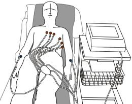
Seeing an ECG being performed will look something like the scene below. As you can see, the peripheral leads are correctly placed on wrists and ankles.
Image: Patient undergoning and ECG
Chest Leads
There are 10 wires on an ECG machine that are connected to specific parts of the body. These wires break down into 2 groups:
- 6 chest leads
- 4 limb or peripheral leads (one of these is “neutral”)
The 6 chest leads are positioned as below:
Image: Positioning of the 6 chest leads
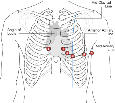
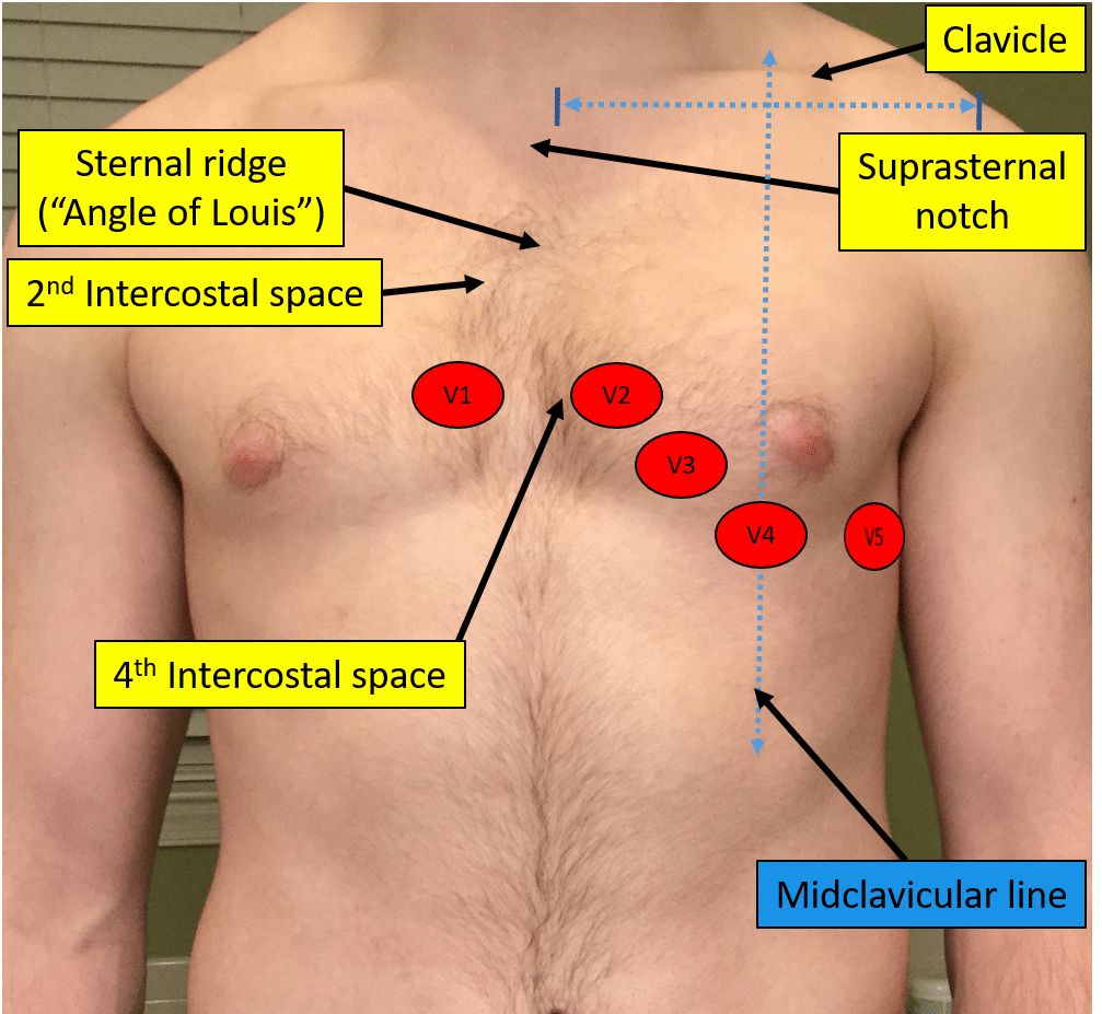
The 6 leads are labelled as “V” leads and numbered V1 to V6. They are positioned in specific positions on the rib cage. To position then accurately it is important to be able to identify the “angle of Louis”, or “sternal angle”.
To find it on yourself, place your fingers gently at the base of your throat in a central position and move your fingers downward until you can feel the top of the sternum, or rib cage. From this position, continue to move your fingers downward until you feel a boney lump. This is the “angle of Louis”.
The angle of Louis is most easily found when the patient is lying down as the surrounding tissue is tighter against the rib cage.
From the angle of Louis, move your fingers to the right and you will feel a gap between the ribs. This gap is the 2nd Intercostal space. From this position, run your fingers downward across the next rib, and the next one. The space you are in is the 4th intercostal space. Where this space meets the sternum is the position for V1.
Go back to the “angle of Louis” and move into the 2nd intercostal space on the left. Move down over the next 2 ribs and you have found the 4th intercostal space. Where this space meets the sternum is the position for V2.
From this position, slide your fingers downward over the next rib and you are in the 5th intercostal space . Now look at the chest and identify the left clavicle, a bone that runs from the left shoulder to the top of the sternum. The position for V4 is in the 5th intercostal space , in line with the middle of the clavicle (mid-clavicular). V3 sits midway between V2 and V4.
Follow the 5th intercostal space to the left until your fingers are immediately below the beginning of the axilla, or under-arm area. This is the position for V5.
Follow this line of the 5th intercostal space a little further until you are immediately below the centre point of the axilla, (mid-axilla). This is the position for V6.
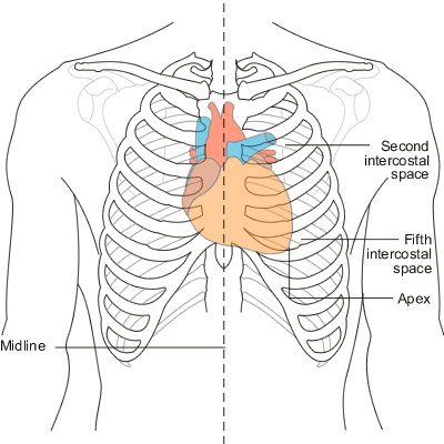
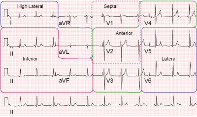
Now look at the picture below showing the position of the heart in relation to the rib-cage and you get an idea as to which areas are being looked at by these leads.
Image: Heart position in relation to the rib cage
